Testing Response Time
Measurement of response time for quality intensification of computer based assessment with the help of hardware setting and software driver
For different research questions it is necessary to capture response times accurately. But how to determine them precisely with the help of computers or smart phones? Does a system cause a constant delay concerning measurement data processing or does it variegate much? Serious products on the free market are calibrated exactly and have to be used as combined systems including both computer-hardware and specially optimized software for the hardware. Can this effort be reduced if certain conditions are valid? The measurement of components, used in different scientific projects like Flux or NEPS, raises the quality of the conducted assessments and improves the software design of response time tests.
Testing Response Time Measurement on PC
Testing the precision of response time measurements is based on a comparison of two independent measurements of response time. Each single value originates from external hardware that also triggers the test. The according comparative value is delivered from the test object itself. Thousands of measurements can be carried out by an automatic process in a short amount of time. 
Basis of the external hardware is a response time keyboard that has been developed from TBA in cooperation with extern partners. The keyboard is equipped with two large and seven small buttons as well as a pulse input. Like an ordinary keyboard it is connected via USB to the computer. The buttons are freely definable and via a second USB-Stack (with the same USB connection) time telegrams are transmitted. With the help of a testing circuit, that provides highly precise rectangular impulses on the pulse input of the keyboard, the accuracy of the time telegrams have been proved.
Time telegrams are captured by a small c-program and transferred to a TCP/UDP port for the examination of response time testing. This program can be compiled under Windows (Visual C++) and Linux (GCC). From this point, the implementation of the data-capturing-software is independent from the platform, language and location of the computer. In the measurements so far Java had been used under Linux.
The pulse input is accessed by an optical sensor that needs adjusted visualisations. Images that are used in the response time testing have to provide a black & white area in a less relevant image section. Images have to be adjusted in a way that does not modify the normal test procedure (‘real conditions’) but triggers the sensor accordingly. Therefore, starting a stimulus creates an accurate time telegram via the pulse input of the response time keyboard. The pushing of a button creates a second telegram. Because the telegrams are generated by an external keyboard, the accuracy does not depend on transmission times to or from the computer. For automatic tests the pulse input of the keyboard is used as a ‘button’ (response to stimulus) likewise via the software (and the optical sensor).
Testing Response Time on Tablets and Smartphones
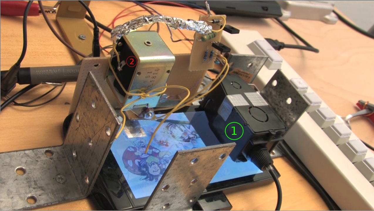
To be also able to administer tests on tablets and smartphones the system has been expanded by an active component, an “electric finger”. A main problem is the reliable activation of the so-called softkeys on touch sensitive surfaces (touchpads). As the functional principle of touchpads bases on a closely limited capacitive change, the activation has to take place via an object of suitable permittivity. Depending on the test objects there are different responsivities.

In a first prototype the finger consists of a stamp with two contact sections that is falling on a pasted conductive surface. The size of the conductive surface has to be adjusted to the responsivity of the touchpads. The contact sections are connected with a button of the response time keyboard, so that they activate a time stamp. The finger can be moved with the help of a solenoid. To control the solenoid a controllable LED of the response time keyboard is used whose signal is routed through a driver stage.
In addition to the set up mentioned above, the optical sensor is integrated and activates the primary time stamp. After a definite time the software makes the electronic finger drop. The touching of the surface activates the secondary time stamp. With this the reaction times outside the test object are identified precisely and can be compared to the data the test object captured itself.

To ensure the relation of the correct values a.) the time between test object and external measurement set up is synchronized when the measurement starts and b.) every measurement is assigned to a unit that is distinct from other units by breaks. Values are only valid and complete units when they can be assigned to each other because of their closeness in time. Because of the abrasion of the conductive surface, the number of valid measurement units decreases gradually.
Usage so far
With the response time keyboard TBA offers a hardware set up with an internal developed optical sensor and electronic finger, including all hard and software driver. So far the set up has been used in the project Flux for validation of measurements and for the preparation of testing the software prototypes used in the context of computer based data assessment for the National Educational Panel.
Further Developments
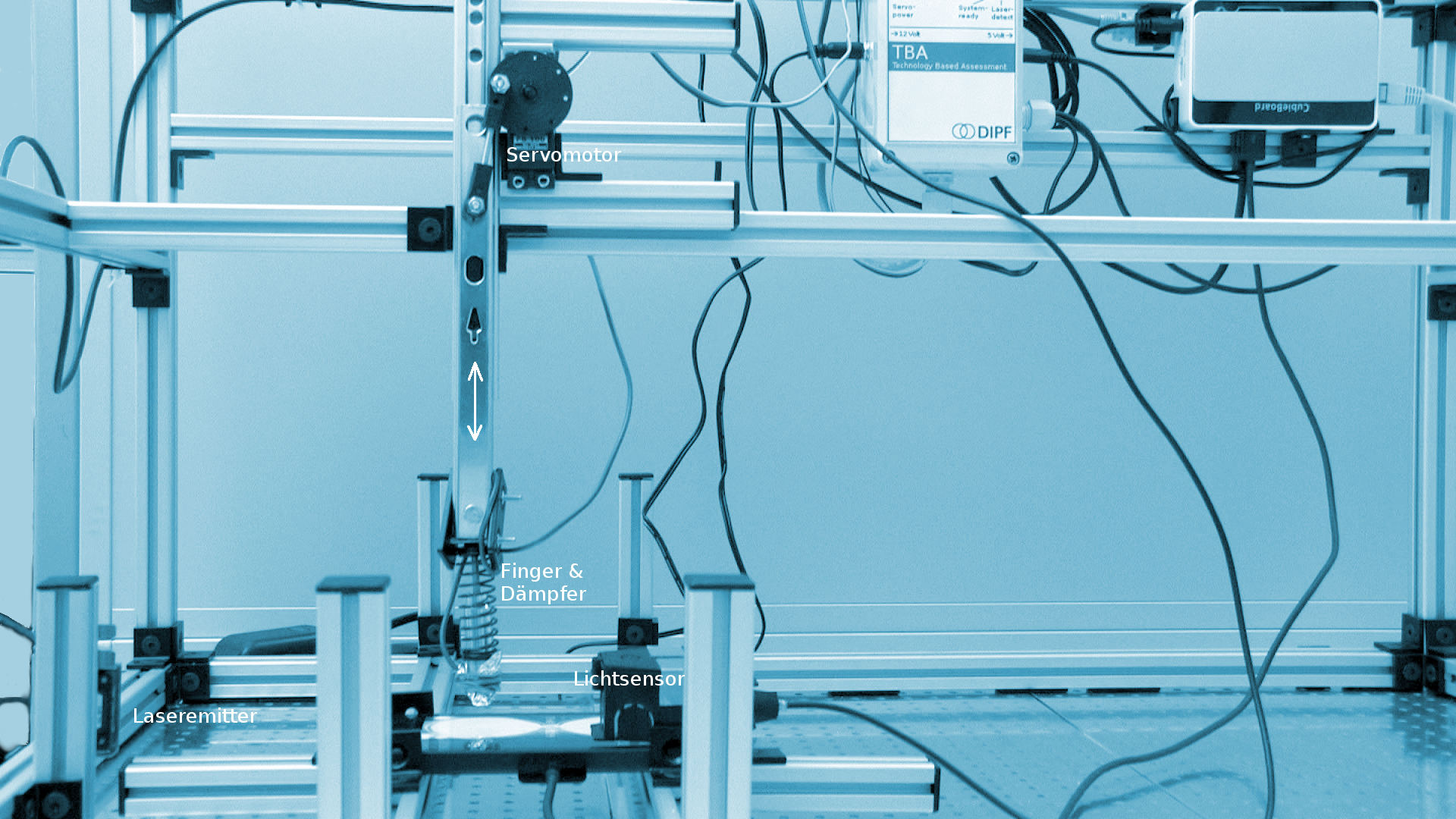
 In an advanced testing set-up different functional principles are used. The finger is moved with the help of a servo from model making and the detection of touching the glass surface is ensured by a laser beam. There is in no way any pulse energy. The machine to be tested is mechanically barely stressed and does not need applications in the form of a conductive contact area. The construction is robust, low-wear and can be used by briefed staff.
The integrity of the datagrams of time recording is secured through the integration of the TBA response time keyboard. The control of the finger and the measurement data processing is done by a monoboard computer (Cubieboard). HDMI-interface and USB-ports allow connecting keyboard, mouse and monitor.
Via Ethernet-network remote controlling is possible. Measuring and control software is running in the embedded system under a debian derivative (Cubian). An additional measuring PC is no longer necessary. The testing set can execute measurement autonomously. The keys of the response time keyboard are assigned to simple function. Machines with a display size of 28 inch can be tested.
Here you can see a total view of the test set-up:

Further details
Funding: Inhouse
Duration: since 2012
Status: ongoing
Contact: Roland Johannes